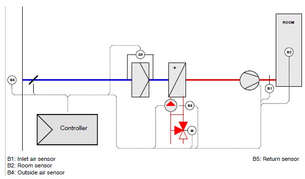
Block circuit diagram 1 for Fans Rosenberg
Inlet air device Heating, with hot water pump, switch box, options:
- Inlet air temperature control
- Room temperature control
Application:
Ventilation system for rooms in which the inlet air temperature or room temperature should be held
constant by warming or cooling the inlet air.
Function:
The temperature measured by the inlet air sensor B1, room sensor B2 or outlet air sensor B3 is compared by the controller with the adjusted set point. In the event of a deviation, the controller displaces the heating valve.

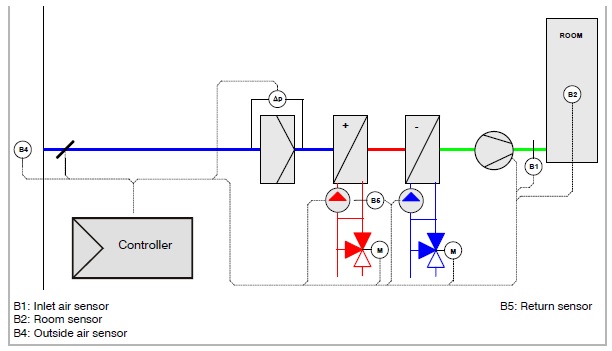
Block circuit diagram 2 for Fans Rosenberg
Inlet air device
Heating with hot water pump; cooling with cold water pump
Switch box, options:
- Inlet air temperature control
- Room temperature control
Application:
Ventilation system for rooms in which the inlet air temperature or the room temperature should be
held constant by the heating or cooling of the inlet air.
Function:
The temperature measured by the inlet air sensor B1, room sensor B2 or the outlet air sensor B3 is compared by the controller with the adjusted set point. In the event of a deviation, the controller displaces the heating/cooling valves.

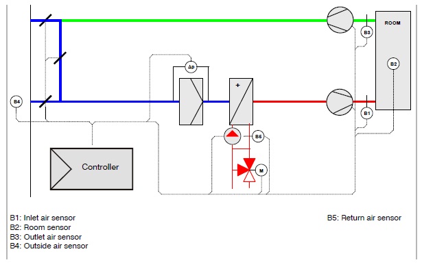
Block circuit diagram 3 for Fans Rosenberg
Inlet and outlet air device
Hot water pump heating
Switch box, options:
- Inlet air temperature control
- Room temperature control
- Outlet air temperature control
Application:
Ventilation system for rooms in which the inlet air temperature or the room temperature should be
held constant by heating or cooling of the inlet air.
The room sensor is placed in the outlet air if no representative measurement value can be located in
the room.
Function:
The temperature measured by the inlet air sensor B1, the room sensor B2 or the outlet air B3 is compared by the deviation control with the adjusted set point.
In the event of a variation, the controller displaces the heating valve.

The contact addresses are to be found in the attachment, or else please phone +49 (0)7940 / 0917 186 894 or email to info@rosenberg.com.vn


